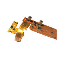
key components of a PCB flex circuit
A PCB flex circuit is an electronic printed circuit board that features flexible copper traces on a non-conductive base. It is ideal for a wide variety of applications, including portable devices such as laptops and mobile phones, and aircraft and unmanned vehicles. A flex circuit also has the ability to bend and fold, which allows it to fit into a more compact form factor than traditional rigid PCBs. This flexibility makes it easy to assemble and install into a variety of applications, reducing manufacturing costs and assembly time.
The main component of a pcb flex circuit is the cladding layer, which provides insulation for the copper. The most popular material for this layer is polyimide, due to its superior thermal control properties. Polyimide can maintain its strength and elasticity over a wide temperature range, making it ideal for use in harsh environments. It also offers outstanding resistance to vibrations and mechanical shocks, making it a highly durable choice for a flex circuit.
Other key components of a pcb flex circuit include the dielectric base layer and the conductors. The base layer is typically made from a polyimide or polyester film. The conductive traces are then etched onto the substrate, using either electro-deposited copper or flexible rolled annealed (FRAC) copper. A coverlay is then applied to protect the layers from moisture, dirt, and damage.
What are the key components of a PCB flex circuit
The thickness of a flex circuit is another important factor. Thicker traces are more difficult to bend, while thinner traces offer greater flexibility. A flex circuit designer will need to strike the right balance between these two factors, depending on the application.
One of the most significant benefits of a PCB flex circuit is its lightweight nature, which can be as much as 75% lighter than a traditional design. This is thanks to the incredibly thin substrates, which are often made from polyimide or polyester films that are as little as 12-120 microns thick.
A flex circuit can also feature localized stiffeners, which can add mechanical support to specific areas of the structure. The stiffeners can be made from materials such as Kapton or FR4. Single-sided, double-sided, and multilayer flex circuits can all benefit from these added features, which reduce the likelihood of failure and increase overall product reliability.
One of the most significant advantages of PCB flex lies in its flexibility, which enables it to conform to irregular shapes and fit into tight spaces that would be impractical or impossible for rigid PCBs. This flexibility opens up a myriad of design possibilities, allowing engineers to create compact, lightweight electronic devices with enhanced performance and functionality. Additionally, the ability to bend and flex reduces the need for bulky connectors and wiring, simplifying assembly and reducing overall manufacturing costs.
PCBWay can also perform an electrical test for a flex circuit, checking to make sure all of the traces are connected and that there is no shorting or cutting. The company can even add a shielding layer to the circuit, which can help to minimize electromagnetic interference (EMI). These options may increase the cost slightly, but they are worth it for the quality of the final product.